From more than 10 years experiences in OEM & ODM services, our sales team and technical team are always available to check and discuss your requirement details. We will make continuous efforts to improve capabilities of R&D, manufacturing and marketing to provide more and more reliable products and bring the best values to every customer.
FAQ
A DC power supply is to supply voltage and current in constant voltage (CV) or constant current (CC) mode within the rated output range. Such working characteristics is called a constant voltage/constant current automatic cross-over type. This permits continuous transition from constant current to constant voltage modes in response to the load change. The intersection of constant voltage and constant current modes is called the crossover point. Below figure shows the relationship between this crossover point and the load.
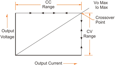
In CV mode, a regulated output voltage is provided. The output voltage remains constant as the load increases while the output current changes in response to the load changes, up till the present current limit point is reached. At that point, the output current becomes constant and the output voltage drops in proportion to the further increases in load.
Similarly, in CC mode, crossover from the CC to CV mode automatically occurs from a decrease in the load. A regulated output current is provided. The output current remains constant as the load decreases while the output voltage changes in response to the load changes.
A power supply with CV and CC operation mode can be operated in only one mode according to load situation. The power supply is in CV mode when the actual load is over the preset load capacity; and the power supply is in CC mode when the actual load is below the preset load capacity.
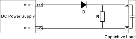
When the power supply is connected to a big capacitive load, it always causes increase to the output voltage in a power supply. The output voltage may make fast increase to the Over Voltage Protection point. It may also cause slow decrease when the output voltage is turned down.
To solve this problem, connect a power resistor in parallel to the output terminals of the power supply; at the same time, connect a diode in serial between output terminals and the load.
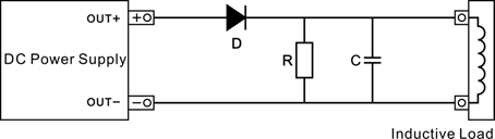
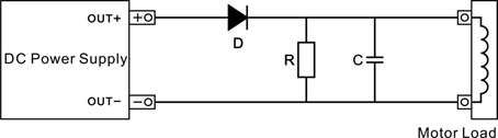
When an inductive load is connected to the power supply, it will cause a reverse polarity induction electric motive force when the power supply is turned on or off, or when preset the output voltage. The pulse noise caused by an inductive load will also affect the power supply, especially when the pulse noise has the same polarity with the output of power supply.
To avoid effect or damage to the power supply, connect a diode in serial between the output terminals of power supply and the load; at the same time, connect a power resistor and a capacitor in parallel to the load to make a R-C snubbed circuit, which will significantly restraint generation of the noise.
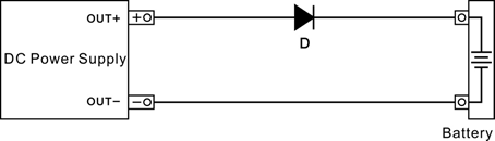
When use the power supply to charge a battery, such as accumulator and ni-mh battery, the recommended protection measures is to connect a diode between the power supply and the battery. When the output electrolytic capacitor of the power supply is charged, connecting a load (battery) may cause sparks. This is normal. After the two of them get to equal voltage, the sparks will disappear.
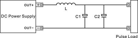
Even if the peak current of a pulse load, such as motor, bulb, DC-DC or DC-AC converter module, does not exceed the rated current of the power supply, it will also cause voltage drop or instability to the output.
A basic solution is to connect a inductor in serial between the power supply and the load. Or, choose a power supply with higher rated current. If the pulse circuit has a small pulse width or low peak current, another solution is to connect a capacitor with large capacity. A reference to choose capacity of a capacity is: 1000uF capacity to a 1A current.
When the power supply is connected to a load that will cause reverse polarity current to the power supply output, the output voltage will increase, because the power supply cannot absorb the reverse polarity current from the load.
A solution is to connect a diode in serial between the output terminal and the load; at the same time, connect a discharge resistor in parallel to the load to absorb the reverse polarity current. When the reverse polarity current is a peak surge, connect the large electrolytic capacitor in parallel to the two ends of the load.
When the power supply is connected to a big capacitive load, it always causes increase to the output voltage in a power supply. The output voltage may make fast increase to the Over Voltage Protection point. It may also cause slow decrease when the output voltage is turned down.To solve this problem, connect a power resistor in parallel to the output terminals of the power supply; at the same time, connect a diode in serial between output terminals and the load.
Contact Us
Contact us or give us a call to discover how we can help.
About Us
Twintex Instrument Ltd. was established in 1998.With honesty, innovation and continuation as the core of enterprise cultural, Twintex has been gradually developed into a test & measurement instruments manufacturer, products including oscilloscope, waveform/function generator, DC power supply, AC power supply, multimeter, LCR meter and other general purpose test & measurement instruments.